

INTRODUCTION
Atlantoaxial joint instability can stem from multiple factors, including trauma, infection, inflammation, and congenital issues. Surgical intervention for atlantoaxial joint instability aims to improve stabilization and alignment. Posterior atlantoaxial fixation is an effective approach for addressing this instability13). The atlas (C1) and axis (C2) constitute unique and complex parts of the spine that differ significantly from other vertebrae.
Posterior transarticular screw fixation is a recognized method of rigid internal fixation in cases of atlantoaxial instability7). Nevertheless, this technique requires technical skill and substantial experience and carries the risk of vertebral artery (VA) injury. Consequently, in 2001, Harms and Melcher5) introduced a screw-rod system for C1-2 fixation. This system offers effective immobilization with fewer complications than alternative posterior atlantoaxial fixation approaches1). Currently, this system is the most frequently used method of atlantoaxial fixation. Numerous adaptations of the original screw-rod system have been documented. However, this system has a potential risk of damage to the surrounding neurovascular structures, including the hypoglossal nerve, VA, C2 nerve root, and internal carotid artery2,10,11).
To avoid neurovascular complications, various entry points have been explored for C1 screw fixation, including the posterior arch (PA) and superior lateral mass (SLM)16). The PA entry point allows for the insertion of longer screws and enhances pull-out strength, comparable with bicortical lateral mass screws3). SLM entry point can be useful in avoiding VA injury (VAI) when there is a persistent intersegmental artery below the C1 arch9,12).
For C2 screw insertion, alternative methods, such as pedicle, pars, or interlaminar screws, exist. If all screw fixations fail, extending the fusion to the caudal level (C3 or C4) is an option. Conversely, in cases of unsuccessful C1 screw insertion, no alternative screw fixation method is available. Extending the fusion to the cranial level (occipital) is a potential solution in such cases. If the head is immobilized in an extended position, the patient may experience challenges with the downward gaze, potentially affecting walking. Conversely, if the head is fixed in a retracted position, difficulties with the upward gaze can lead to swallowing issues. This is believed to stem from fixing the neck in a flexed or chin-tucked posture, resulting in reduced oropharyngeal space and impeding spinal movement during the swallowing process8).
Intraoperative fluoroscopy and other guidance methods are used for precise screw placement. Lateral intraoperative fluoroscopy helps prevent misplacement in the superior and inferior directions, although the anteroposterior view can be limited by bone overlap. However, these approaches are time-consuming and require radiation exposure. Therefore, we believe that meticulous dissection of the C1 PA to improve anatomical understanding is crucial for enhancing the accuracy of C1 instrumentation rather than relying solely on intraoperative fluoroscopy. Hence, we aimed to assess variations in the atlas anatomy and evaluate the efficacy of the freehand screw placement technique in C1.
MATERIALS AND METHODS
A retrospective analysis was performed using radiological parameter data and medical records of patients who underwent posterior C1 instrumentation using the freehand technique from April 2019 to January 2023. The inclusion criteria were as follows: (1) patients requiring C1 screw fixation; (2) patients who underwent pre- and postoperative radiological assessments using plain radiographs, thin-slice computed tomography (CT), and angiographic CT; and (3) patients with complete medical records. Data on patients’ age, sex, diagnosis, and complications were collected.
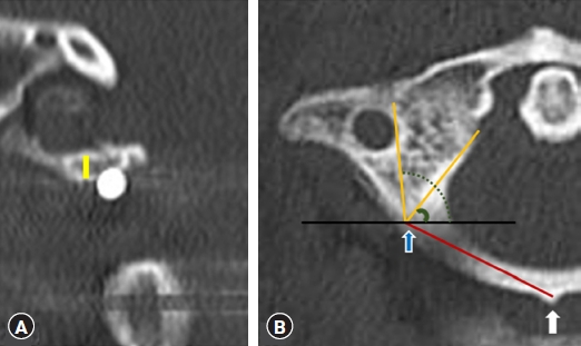
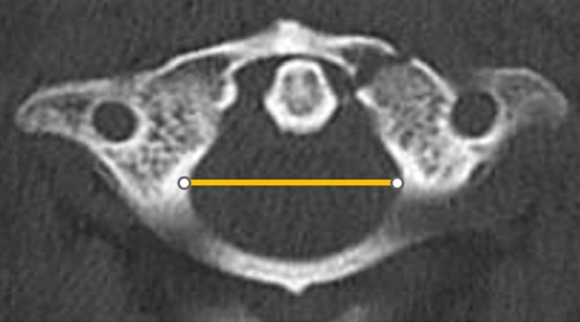
Morphometric measurements of 30 healthy individuals and 22 patients who underwent surgery were obtained from preoperative CT scans of the bilateral pedicles at the C1 level. Coronal, axial, and sagittal CT reconstructions were examined to ascertain the distance from the screw entry point to the midpoint of the C1 posterior tubercle, the diameter of the central canal of the atlas, screw convergence angle, the height of the C1 PA at the screw entry point, width of the canal. (Fig. 1, 2).
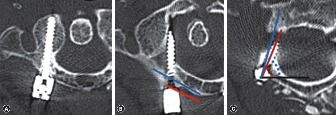
Breach rates were determined from the axial and coronal reconstruction images of postoperative CT scans (Fig. 3). The severity of breaches reflected the percentage of screw diameter beyond the cortical edge (0, cortical touch; I, ≤ 25%; II, 26%-50%; III, 51%-75%; IV, 76%-100%).
Surgical Techniques: C1 PA Screw Placement
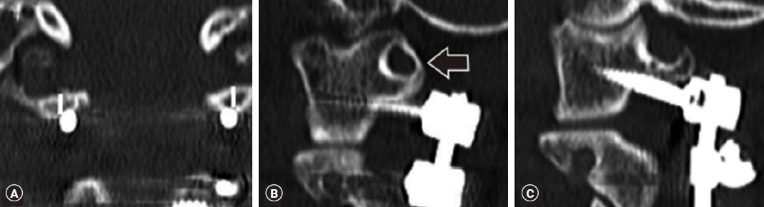
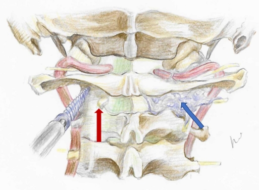
The C1 PA was subperiosteally dissected using gauze and a Cobb elevator along the PA in the mediolateral direction. Subsequently, a nerve freer or Penfield Dissector No. 4 was utilized in the craniocaudal direction. The screw entry point was established 23 mm laterally at the midpoint of the PA. In cases where the thickness of the PA was <4 mm, a “notching technique” was applied (Fig. 4). The VA, situated above the PA, was safeguarded with Penfield Dissector No. 2, whereas the entry point was decorticated using a 2.0-mm burr. The entry hole was expanded in depth and width using a 2.5-mm diameter drill bit and widened further with a 3.0-mm diameter drill bit to a depth of 26 to 30 mm, measured with a preoperative CT scan axial image. Using this serial dilation technique, we inserted the pedicle screw in the C1 pedicle at a diameter of less than 4 mm. Palpation with a ball tip probe to check for wall violations and hole depth was done during each step. The trajectory was determined by looking directly at the pedicle. A 26 to 30-mm long screw with a diameter of 3.5 mm was inserted. The Vertex Reconstruction System (Medtronic, Dublin, Ireland) was used in all patients. After inserting the screws, 3.0-mm rods were applied and fastened using cap nuts.
RESULTS
In the 30 healthy individuals, the anatomical length of the structure passing through the entry of the C1 screw was measured. The medial and lateral angles were also measured at the screw insertion points to establish a safe angle that did not invade the transverse foramen and spinal canal. As the C1 screw entered, the average width of the C1 PA was found to be 5.3 (range, 3.3-6.4) mm, the height of the C1 pedicle was 5.5 (range, 4.1-8.9) mm, and the distance from the screw entry point to the midpoint of the C1 posterior tubercle was 23.8 (range, 18.7-28.5) mm. We found an average medial angle of 54.1° (range, 41°-71°) and a lateral angle of 98.4° (range, 88.5°-108°) for the C1 screw entry points (Table 1).
The anatomical length of the structure passing along the entry of the C1 screw in 22 operated patients was measured, and the medial and lateral angles at the screw insertion points were measured to determine a safe angle that did not invade the transverse foramen and spinal canal. As the C1 screw entered, the average width of the C1 PA was found to be 4.8 (range, 3.2-5.8) mm, the height of the C1 pedicle was 5.1 (range, 2.9-6.2) mm, and the distance from the screw entry point to the midpoint of the C1 posterior tubercle was 23.5 (range, 19.1-28.4) mm. We found an average medial angle of 60.1° (range, 52°-75°) and a lateral angle of 96.1° (range, 89°-112°) for the C1 screw entry points (Table 2). "healthy individual" and "Patient group" did not show statistically significant differences in the ideal entry point.
Seven breaches were observed, all of which were medial. The breaches were classified as Grades I, III, and IV in 4 (57%), 2 (29%), and 1 (14%) cases, respectively. The breaches occurred on the right side in six cases and on the left in one case. The C1 screws were PA screws, and if there was a narrowed PA, PA notching was performed (Table 3).
DISCUSSION
Posterior C1-C2 screw instrumentation for immediate rigid atlantoaxial fixation was first described by Goel and Laheri in 19944). This technique was subsequently popularized by Harms and Melcher in 20015), after which C2 pedicle cannulation became a commonly performed technique. Both lateral mass and PA screws are viable options for atlas fixation. PA screws have superior resistance to pull-out via the axial load than lateral mass screws in the atlas18). The mean pull-out strength of the C1 lateral mass screws was 821 N (range, 387-1,645; N ± standard deviation [SD], 364 N). The mean pull-out strength of the PA screws was 1,403 N (range, 483-2,200; N ± SD, 609 N). Therefore, in our study, most of the C1 screws were inserted through the PA entry point.
He et al.6) reported that C1 fixation via the PA entry point was less invasive and simpler, had fewer complications, and offered better fixation results. However, the PA entry point could have a higher probability of VAI and increase the risk of a C1 arch fracture. Yi et al.17) revealed that the PA entry point was an independent risk factor for screw malposition and total C1 screw complications. Moreover, PA screw placement is not always possible due to the anatomical variability of the C1 arch. The application of C1 screw fixation using the PA entry point is generally limited to a 4-mm height of the C1 arch15).
A comprehensive understanding of the optimal entry point with PA morphometry is crucial to prevent intraoperative complications, such as VAI and neural trauma, particularly during lateral dissection and procedures, such as C1 decompressive laminectomy (LM), LM, or pedicle screw insertion. In the conventional C1 screw insertion technique, in which the entry point lies between the PA and LM, surgeons often opt for a higher point on the posterior aspect of the PA to minimize venous bleeding and potential C2 nerve root damage. However, this placement increases the risk of VAI, particularly if the artery traverses the arcuate foramen.
In our study, preoperative evaluations included lamina thickness and pedicle height assessed via thin-slice CT, along with VA anatomical assessment using CT angiography. Patients with a ponticulus posticus or anatomical insufficiency were managed accordingly.
As a result, six patients had medial breaches. The causes of malposition were as follows: the distance from the screw entry point to the midpoint of the C1 posterior tubercle was shorter than others (two cases; 23.8 vs. 15.97 mm), and the medial screw trajectory angle was smaller than the medial safety angle (54.1° vs. 52.7°). There were more right breaches than there were left breaches because the right medial angle was larger than the left one was.
The procedure involved delineating the medial and lateral borders of the C1 lateral mass and pinpointing its midpoint. Subsequently, a screw was directly inserted. Our anatomical measurements yielded a safe entry point distance of 23.8 mm and a trajectory angle of 54.1°. Additionally, when the height of the C1 arch was <4 mm or the ponticulus posticus was present, the C1 notching technique was used for screw insertion. This involved selecting an entry point situated between the entry points of the C1 lateral mass screw and the C1 PA screw, precisely at the junction of the C1 PA and lateral mass. This entry point was slightly distant from the paravertebral venous plexus and C2 nerve root. This higher-than-usual entry point helped minimize venous bleeding and the potential for C2 nerve injury (Fig. 5)14).
This study has limitations, including its retrospective and single-center design and non-blinded nature. Moreover, the sample size was small. Furthermore, our study focused solely on evaluating the safety of the instrumentation technique and did not provide insights into the long-term and functional outcomes of the patients.
CONCLUSION
The freehand technique for inserting screws at the ideal entry point into the C1 vertebra is safe and effective, obviating the need for intraoperative fluoroscopy or navigation. Our study demonstrates that preoperative anatomical assessment for surgical planning, coupled with intraoperative tactile feedback, can contribute to precise screw placement.